
AP 3302 Pt. 3
Section 2
CHAPTER 6
Free Running (Astable) Multivibrators
A few of the basic actions which occur time and again in pulse circuits are summarized below:
a. If the control grid of a pentode valve is below cut-off, no valve current flows whatever the voltages on the screen, suppressor or anode.
b. If the control grid rises above zero volts with respect to cathode, grid current flows. The grid-cathode resistance is then very low, typically 1kW. If a high resistance is connected between the grid and a point of high voltage, grid limiting takes place to 'clamp' the grid to just above zero volts.
c. If a valve is conducting, its anode voltage Va is decided by its anode current Ia, the load RL and the value of h.t. Thus if Ia is 5mA, RL 10kW and h.t. 300V, then Va must be 250V whatever other parts of the circuit may be doing. If a valve is cut off, its anode voltage rises, usually to the value of the h.t. supply; it may rise even above h.t. if 'ringing' takes place (see p 81).
d. CR series networks form an important part of most
pulse generator circuits. The effects of applying sudden changes of voltage
to such circuits are discussed in detail in Chapter 2 of this section (p
67). There we said 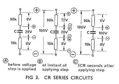 that
a capacitor cannot change its charge, and hence the voltage across it, instantaneously.
Thus if 100V is suddenly applied to C and R in series the full 100V appears
across R initially; C then commences to charge on a time constant CR seconds.
These statements also apply if there is more than one resistor connected in
any series order with C; the 100V is initially shared between the resistors
according to their value. If the capacitor is initially charged to, say, 20V
before the step is applied then the difference (80V) is initially shared between
the resistors (Fig 3b). In each case as C charges so the voltage across it increases
and the voltages across the resistors decrease (Fig 3c).
that
a capacitor cannot change its charge, and hence the voltage across it, instantaneously.
Thus if 100V is suddenly applied to C and R in series the full 100V appears
across R initially; C then commences to charge on a time constant CR seconds.
These statements also apply if there is more than one resistor connected in
any series order with C; the 100V is initially shared between the resistors
according to their value. If the capacitor is initially charged to, say, 20V
before the step is applied then the difference (80V) is initially shared between
the resistors (Fig 3b). In each case as C charges so the voltage across it increases
and the voltages across the resistors decrease (Fig 3c).
e. The combination of valves and CR circuits forms the basis of most pulse generators. Suppose a CR network is connected to two valves as shown in Fig 4. If V1 is conducting, its Va is decided by the valve current, by RL1, and by the ht. If Va is + 30V (170V developed across RL1) and remains steady at this value then C1 will charge to 30V. There is then no voltage across Rg1, and point B is at zero volts (Fig 4a). If now V1 is suddenly cut off we have 170V (the ht of 200V less the 30V across C1) shared between RL1 and Rg1 in proportion to their values. Thus, at the instant V1 cuts off point A rises to + 185V (15V dropped across RL1) and point B rises to + 155V (155V across Rg1). C1 is unaffected instantaneously and remains charged to 30V (Fig 4b). C1 now commences to charge through RL1 and Rg1 and will eventually charge to 200V; the voltages across RL1 and Rg1 will then both be zero. Point B is thus at zero volts and A at + 200V (Fig 4c).
In this simplified explanation: we have ignored the effect that V2 has on the circuit when this valve is suddenly switched on. We shall consider this point, and others, later.
However, the important factors to bear in mind are that when one valve is suddenly cut off its anode voltage rises rapidly towards ht+. This full rise of voltage is transferred to the grid of the other valve through the capacitor (which cannot change its charge instantaneously) and this other valve is immediately driven hard on. We thus have switching between two valves. Somewhat similar remarks apply also to transistors.


