
AP 3302 Pt. 3
Section 2
CHAPTER 6
Free Running (Astable) Multivibrators
Interval A to B. C1 charges through RL2 causing VB1 to return to zero and VC2 to rise towards - 12V with a time constant of C1RL2 seconds. C2 discharges through R2 and VB2 rises towards the negative aiming voltage with a time constant of C2R2 seconds.
Instant B. As soon as VB2 rises through cut-off TR2 starts to conduct and a second avalanche takes place with the roles of TR1 and TR2 reversed in relation to those at instant A. This second avalanche cuts off TR1 and leaves TR2 conducting. VC2 falls rapidly to its working value, VB2 rises above zero volts, VC1 rises by the same amount and VB1 falls to a positive value well beyond cut-off. Thereafter the action is repeated.
The output may be taken from either collector or from both. The remarks made earlier about control of frequency and symmetry and the use of an aiming voltage are applicable to this circuit also. In addition the circuit may be synchronized by applying negative-going sync pulses to one or the other or both bases.
Emitter-coupled Emitter-timed Multivibrator
Steeper leading edges can be obtained, as in the cathode-coupled multivibrator, if the capacitor connected to the output electrode can be eliminated. In the cathode-coupled multi-vibrator V2 anode had no coupling capacitor connected to it so that V2a output had very steep leading edges. The transistor equivalent is the emitter-coupled, emitter-timed circuit shown in Fig 19a. The action may be explained with reference to Fig 19b.
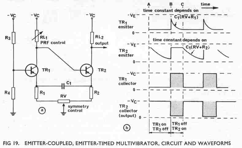
If we assume that TR1 is conducting initially, its emitter and collector voltages are both at a value slightly above earth ('negative up' waveforms); the actual value depends upon the resistors R1 and RL1. TR2 is then cut off because its base is at the same voltage as TR1 collector and its emitter is held negative with respect to its base by the charge on C1. TR2 collector is thus at the negative supply voltage level.
Interval A to B. With TR1
conducting, C1
commences to charge in the opposite direction through RV, R2
and RL1 on
a time constant of
C1(RV
+ R2 + RL1)
seconds. As it does so the voltage at TR2
emitter falls towards earth. The collector voltages remain the same as at instant
A so long as TR1
is on and TR2
off.

