
Linesman/Mediator system
Radar HF 200 Height finder
 A
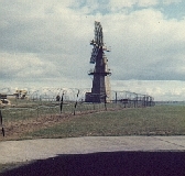
Decca HF 200 height finder at RAF Boulmer with the RX12874 Passive
Detection aerial and the redundant Type
80 modulator building in the background on the extreme
left.
A
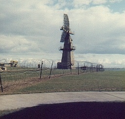
Decca HF 200 height finder at RAF Boulmer with the RX12874 Passive
Detection aerial and the redundant Type
80 modulator building in the background on the extreme
left.
- The height finding element of the Linesman system, the HF 200 succeeded the American AN/FPS-6 height finder radars used in the Rotor system. The HF 200's (along with the AN/FPS-6) were also known as "Nodding Horrors" and they spewed hydraulic oil everywhere. HF 200 Mk3's were located at the three main linesman sites at R.A.F. Boulmer, R.A.F. Staxton Wold and R.A.F. Neatishead. A Mk4 was commisioned at R.A.F Saxa Vord in the Shetland Islands in 1979 and there was a Mk2 at R.A.F. Troodos, Cyprus. Dave Quantrill tells me that the Troodos Mk2 featured a valve console among other things and that it was a horrible thing!
- Note the barbed wire in the picture; for many years Linesman sites were protected only by a wire mesh perimeter fence but in the mid '70's the Ministry of Defence must have bought a job lot of barbed wire cheap from someone because they put it up everywhere! Interestingly enough no one seems to have considered what could be done about air strikes, mortars and rocket propelled grenades - the site was totally undefended from aerial attack and the perimeter fences were not patrolled!
- Once upon a time all of the antennas at R.A.F. Boulmer were painted in a pale blue shade, quite pretty really, and it has been suggested that this was to satisfy the whims of the then Duke of Northumberland who happened to own the land on which the operations site stood, or so the story went. Eventually though someone thought they really should be camouflaged so they were painted in a shade that in Scotland might be called "Sharnie Green"!
- Concise details of radar Type HF 200: (From Annex E to AP 3401, Chapter 22)
|
1. Class of Equipment. 2. Purpose of
Equipment. 3. Frequency. 4. Coverage. 5. Coverage in
Volumetric Role. 6. Range
Performance. |
7. Discrimination. 8. Aerial Characteristics. 9. Aerial Reflector. 10. Aerial Feed. 11. Transmitter. 12. Receiver. 13. Signal Processing. 14. Accuracy. |
Editors note: I am indebted to Kelvin Holmes for providing the technical details of the HF 200 and to Frank Lovett and Dave Quantrill for their contributions.
Height finder radar aerial radiation patterns feature narrow vertical and broad horizontal beam widths. The aerial nods up and down at 20 or 30 cycles per minute and can rapidly slew in azimuth to face the bearing of the target that you want to find the height of.
The Range Height Indicator (RHI) display shows range against height on a CRT. The required target was marked on the height operators display by a strobe that was initiated from a PPI operator's console. Initiating this strobe caused the height finder radar to swing around to face the target azimuth (Azication). The height operator aligned his cursor to the centre of the indicated radar paint on his height display and the height was then calculated by equipment in the Radar Office. In the Rotor system the calculated height was then displayed on an indicator adjacent to the operator console requesting the height, can anyone tell me how HF200 height information was processed in Linesman please?.
