
AP 3302 Pt. 3
Section 2
CHAPTER 6
Free Running (Astable) Multivibrators
|
|
|
|
|
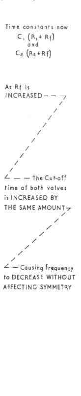
This may be done by the symmetry or pulse duration control Rs shown in Fig 11. When the wiper arm of Rs is at the centre position, the resistance of both CR circuits is the same and the output is symmetrical. The effect of moving the wiper from left to right is illustrated in Fig 11. As the time constant C2R2 decreases, that of C1R1 increases by an equal amount (assuming C1 = C2). Symmetry is therefore varied without affecting the frequency.
Modifications to the Basic Circuit
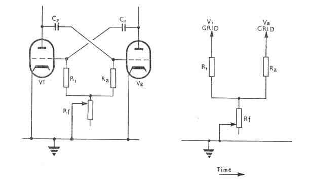
In a multivibrator the change-over from the relaxation period to the avalanche occurs when the grid voltage of the non-conducting valve rises above cut-off. In the circuits considered so far we have shown the grid leaks R1 and R2 connected to earth. The coupling capacitor connected to the grid of the cut-off valve is therefore discharging towards earth and is said to be 'aiming at zero volts'. Since the cut-off point is relatively near zero volts the capacitor discharge is nearing the 'flat' part of its exponential curve. This slow rise through cut-off gives an indeterminate cut-off point, because any slight variations in the circuit conditions (e.g. variation in h.t. supply) will cause the cut-off point to be reached sooner or later than anticipated. Frequency and symmetry may thus vary (see Fig 12).

